|
This document analyses electric motors below 12mm in diameter and compares their specifications. It provides precise data to those willing to optimize a propeller for a given motor-gearbox, or select a gearbox according to the selected motor and propeller. Coreless motor theoryCoreless motors have a quite simple model (figure 1). The torque is proportional to the current; the torque constant k, expressed in [mNm/A] depends on the size and design of the motor. At zero speed (stall), the torque Ms [mNm] and the current Is [mA] are at maximum. With the speed, a back-EMF develops until the torque reaches zero, at no-load maximum speed No [RPM]. A current Io [mA] remains to compensate for the friction. The effective power reaches a maximum at half the maximum speed, that is also half the maximum torque. The electrical power is higher due mostly to ohmic dissipation. The efficiency reaches a maximum at a theoretical value of 17% of the No maximum speed, far from the maximum power value we are interested in.
The coil resistance R is the other important parameter along with the torque constant. It gives a rough idea of the motor power, for a given voltage. The coil current generates the torque, that is, mechanical power. The coil resistance generates heat that degrades the motor characteristics and may destroy it. The dissipated power is proportional to the square of the current. Overcurrent, due to a blocked motor or overvoltage, results in a quick overheat, and possible destruction of the motor. Over speed is also destructive for the brushes. The no-load current is related to friction from the sleeves and brushes, and is worse the greater the miniaturization. For instance, Io/Is is 1% for a 26mm Maxon, Minimotor or Portescap motor, 2% for the MS08, 15% for the Mk10, 17% for the MK06 and 30% for the MK04. Talking about the power of a motor is complicated. Power depends on the voltage, and one can increase the voltage until the motor explodes. Serious manufacturers document a maximum torque, speed and power, taking care of life-time and parameter stability. The life-time of a motor is specified at the nominal voltage and power (1000 hours, 100 hours for pager motors). The life-time is mostly conditioned by brush wear, which is roughly inversely proportional to the dissipated power. Indoor hobbyists are used to overpowering their motors and change the motor or the brushes frequently. We will try to recommend a voltage that allows for a more comfortable lifetime of about 10 hours. Formulas and test bench
Maximum powerThe well known linear plot of Figure 3 shows the current and torque as
a function of the rotation speed,which is an easy parameter to measure.
When the voltage increases, the two curves moves up, and the no-load rotation
speed increases. Manufacturers document their motors for a nominal voltage
only. Slow flyer motors are over volted in order to get more power for
the same weight; a factor of two to three can be applied but the specs
degrade when the motor is hot.
Logarithmic plotsLogarithmic scales are efficient to plot small and large values with the same relative precision. Straight lines, except the ones passing by the origin, are transformed into curves, and all curves of the type y = x^n (e.g. a parabola or an hyperbola) appear as straight lines. If we plot the torque as a function of the rotation speed, the constant-power hyperboles are 45 degrees straight lines on a logarithmic plot (same x-y scale). The transmitted power is maximum at half the stall torque Ms, that is
also half the no-load speed No. We are only interested in the part
of the curve around the maximum transmitted power. On the logarithmic
plot, the straight line torque vs. RPM becomes a curve that is always
the same shape, and the maximum power point moves at 45 degrees when the
voltage changes.
DIDEL's motor specificationsFor slow flying applications, a motor is mainly characterized by its max power within a voltage range. That power is rougly proportional to the square of the voltage. The power coefficient allows computing the power when the voltage is measured. The following table surveys the motors measured by DIDEL. Click on the motor number to get the Excel data and graphs if you want to get more details on a given motor. You can also see the Excel file that built figures 6 and 7. Explanations on the column content follows the tables. The important columns of this table are the max power parameters — which depend on the voltage, as long temperature does not degrade the characteristics at high voltage. At low voltage, friction is also important, but we do not try to work in this range.
Figure 6
See also for the MS08 the API-Portescap 08GS61-107 manufacturer's specs Not sold by DidelThese motors have been selected to compare with other 6mm page motors, and have a reference point with 12mm motors used on slow flyers.
Figure 7
NA06-12 is a pager motor from Namiki. BC06-4 is the 6mm pager motor from BitCharger. A12 is the A-Max 12mm 2.4V from Maxon. Mab12 is a Mabuchi-like core motor. DC5-2.4 is a coreless from Wes-Technik. Tables legendMax power is the best operating point +/- 20% is still acceptable Quality factors
Comparison plot
If you are concerned about battery weight, the current you need to achieve
a given power, that is a given propeller thrust, is your concern. The
battery's voltage drop depends on its capacity per element. You cannot
drive a DC5-2.4 with a 70 mA set of cells. The Current constant allows
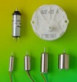
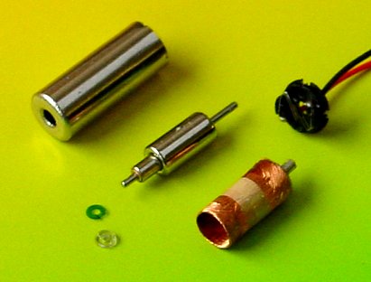
estimating the current for a given voltage. Gearboxes and propellersSee our gearbox section to see what DIDEL proposes as propeller gear trains. If you measure your propeller, you can find the best match.Note on pager motorsDIDEL gets its pager motors from Jinlong Machinery, Hong-Kong (http://www.kotl.com/). They are very primitively documented. We selected several 4, 6, 7, and 10mm motors, with high resistance coils whenever possible, in order to reduce the consumed current for small robots, or allow a higher battery voltage for slow flyers. These motors are very well built, but one has to understand their construction to avoid any damage to the brushes when assembling. It is not possible to put any axial force on the axes. This is a major problem when inserting gears (see gear insertion recommendations).
|
|||||||||||||||||||||||||||||||||||||||||||||||||||||||||||||||||||||||||||||||||||||||||||||||||||||||||||||||||||||||||||||||||||||||||||||||||||||||||||||||||||||||||||||||||||||||||||||||||||||||||||||||||||||||||||||||
 |
CH-1092 Belmont/Lausanne Switzerland Tel +41 21 728-6156 Fax -6157 |